


UCE-DSO212 with UCE-CT212 Combo Deals
Buy more, Save more ...
Description
This product is retired.
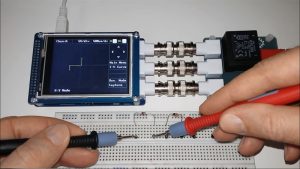
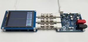
This combo set performs DC parametric characterization of transistors, thyristors, diodes, SCRs, MOSFETs, optoelectronic components and other semiconductor devices. By buying this set, you can have a 2-channel oscilloscope, signal generator and component tester.
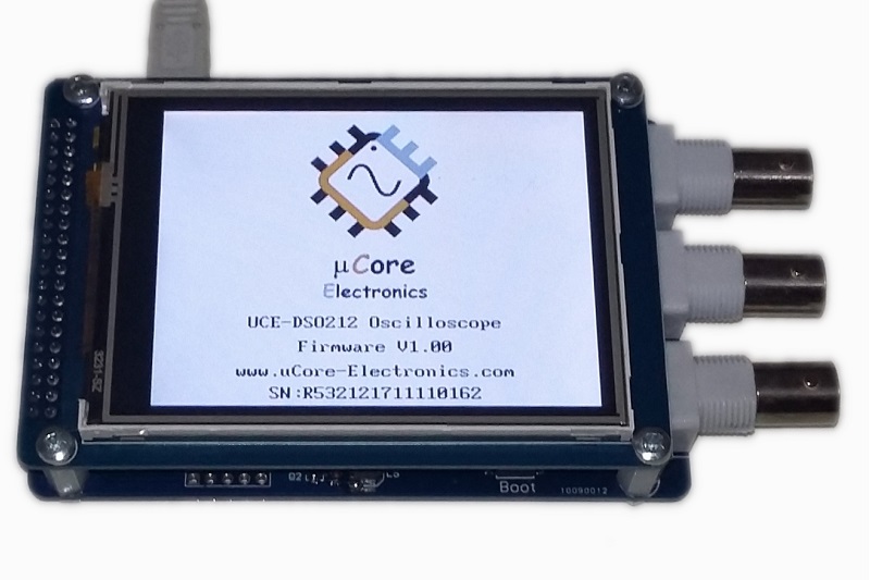
Technical information of UCE-DSO212
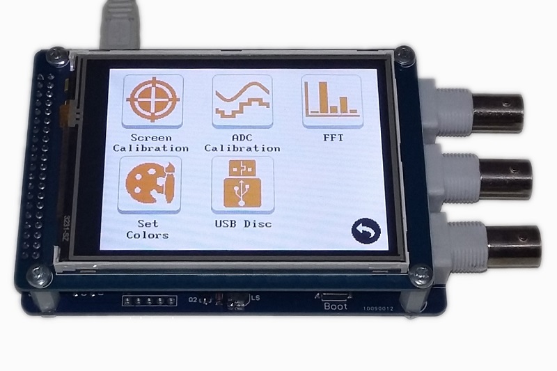
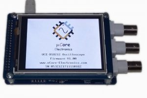
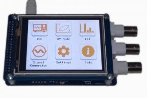
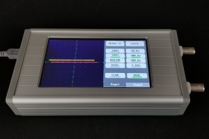
- Display: 3.2 inch 320 × 240 pixel color LCD
- Personalisation: customization of display colors
- Two channel input, One channel signal output
- XY Mode
- Analog Bandwidth: 1MHz
- Maximum sampling rate: 10Msps 12-bit
- Sampling depth: 7.2ksps
- Input impedance: 1MΩ
- Vertical sensitivity: 50mV/div~50V/div
- Horizontal sensitivity: 1.25us/div~500ms/div
- Max input voltage: ±32V (X1 Probe), ±320V (X10 Probe)
- Coupling: AC/DC
- Supply voltage: 5V (mini USB)
- Trig modes: Run, single, Hold functions
- Trigger functions: rising / falling edge, Triggering Cursor
- Auto Measurement: frequency, ton time, toff time, period time, peak-to-peak voltage, mean voltage, RMS voltage
- Test signal: 1KHz %50 duty-cycle square wave, 2.0Vpp
- Cursor: differential measurement for time and voltage
- FFT analyze: 512 points FFT analyze
- Signal generator: Sinus, Square, Triangle, Sawtooth, Arbitrary, Tangent, Logaritmic, Coded pulse, Verticaly-cut sine wave, Sinusoidaly modulated square wave. (-5.0~5.0V, 1Hz~100kHz)
- Storage: internal 128MB USB disk for storing waveform image and firmware upgrade (bootload)
- Menu language: English
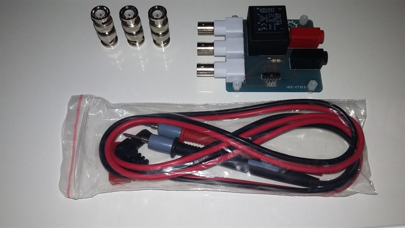
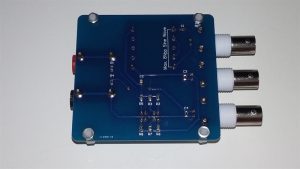
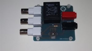
Technical information of I-V Curve Tracker
- Power on by UCE-DSO212. No need any external power supply
- Voltage 52Vp-p (±26V)
- 3 x Current Ranges 100uA/V , 1mA/V and 10mA/V
- Max current 3mA
- Current Limit Switch for semiconductor testing 400uA for 100uA/V range , 2.5mA for 1mA/V range and 3mA for 10mA/V range
- Freq. 50Hz or 60Hz.
Package List:
- 1 pc UCE-DSO212 3.2″ TFT Digital Oscilloscope
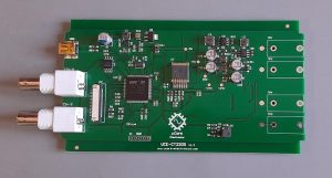
- 1 pc UCE-CT212 Curve Tracer Adapter Unit
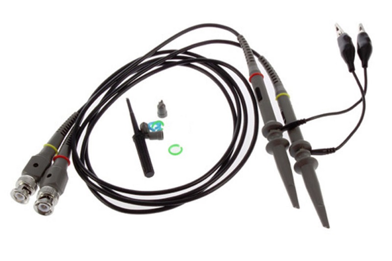
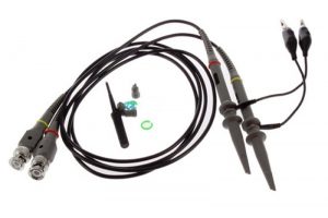
- 2 pcs X1, X10 Probe
- 1 pc touch pen
- 1 pc USB cable
- 1 pc Test Probes
- 3 pcs BNC Adapter
Additional information
| Weight | 620 g |
|---|---|
| Dimensions | 20 × 13 × 6 cm |
| Device Type | Oscilloscope + Signal Generator + Curve Tracer |
|---|---|
| Oscilloscope mode | |
| Signal generator | |
| Short-circuit finder | |
| Tracer Channel | 1 |
| LCD | 3.2 inch (320x240 pixel) |
| Waveform | Sine |
| Frequency | 50Hz, 60Hz |
| Open circuit Voltage | Adjustable up to ±26V |
| Resistor | 100Ω, 1kΩ, 10kΩ (Max current 3mA) |
| Internal disk | |
| Database | NA |
| Database Test | NA |
| Capacitance Meter | NA |
| Ohmmeter | |
| HDMI out | |
| Internal battery | |
| Mouse support | |
| Carrying Case | NA |
| Usage | Amateur |
2 reviews for UCE-DSO212 with UCE-CT212 Combo Deals
Related products
-
UCE-LCR-1 LCR Meter for UCE-CT321L
Price range: $79.90 through $124.90 Select options This product has multiple variants. The options may be chosen on the product page -
UCE-DSO212 with UCE-CT213 Combo Deals
$169.90 Read more -
Sale!
UCE-CT220S Main Board
Original price was: $299.00.$275.00Current price is: $275.00. Read more -
UCE-CT220L Fault Locator & Curve Tracer
Price range: $329.00 through $453.00 Select options This product has multiple variants. The options may be chosen on the product page
John Conarpe –
Quality made, when using with the curve tracer it’s a bit awkward due to the BNC junctions, but functionally helpful. I have an idea for piggybacking the scope and tracer boards eliminating the need for the BNC connectors making a nice portable multifunctional tester.👍🏼
Dave Bos –
Very useful in fault diagnosis. I mounted the oscilloscope on a phone stand with the CT212 PCB mounted underneath and connections made using a combination of straight and 90 degree BNC coupling connectors. Powered by a power bank mounted on the phone stand base to create a complete stand alone unit easily moved and used by engineers. Any firmware updates available?